
The WebDocCam stand is designed to be produced in batches and cheaply. Actual assembly takes about 10 minutes once the parts are in-hand (and allowing for overnight setting of epoxy).
- 3D printed parts: Just two STL files that make all the 3D printed parts, including the base, the camera mount swivel, the alignment plug, the camera screw thumbwheel, and the rotation limiter collar. It would be a single file but considerable time could be saved by printing the base on one printer, the head components on the other.
- PVC parts: Cut two pieces of 1/2-inch schedule 40 pipe, 37.5 cm for the vertical post and 12 cm for the cantilever. You will also need one 90-degree elbow and one T-fitting.
- Metal parts: Two 1/4-20 nuts, one 3.5-inch 1/4-20 carriage bolt, one 1/4-inch fender washer, and one 1/4-20 bolt 3/4-inch long.
(Right-click images below and choose “Open image in new tab” for detailed viewing. This is especially necessary for the exploded view and the “assembling the camera screw” image.)

WebDocCam in webcam mode. Turn the head toward you and tilt the camera up 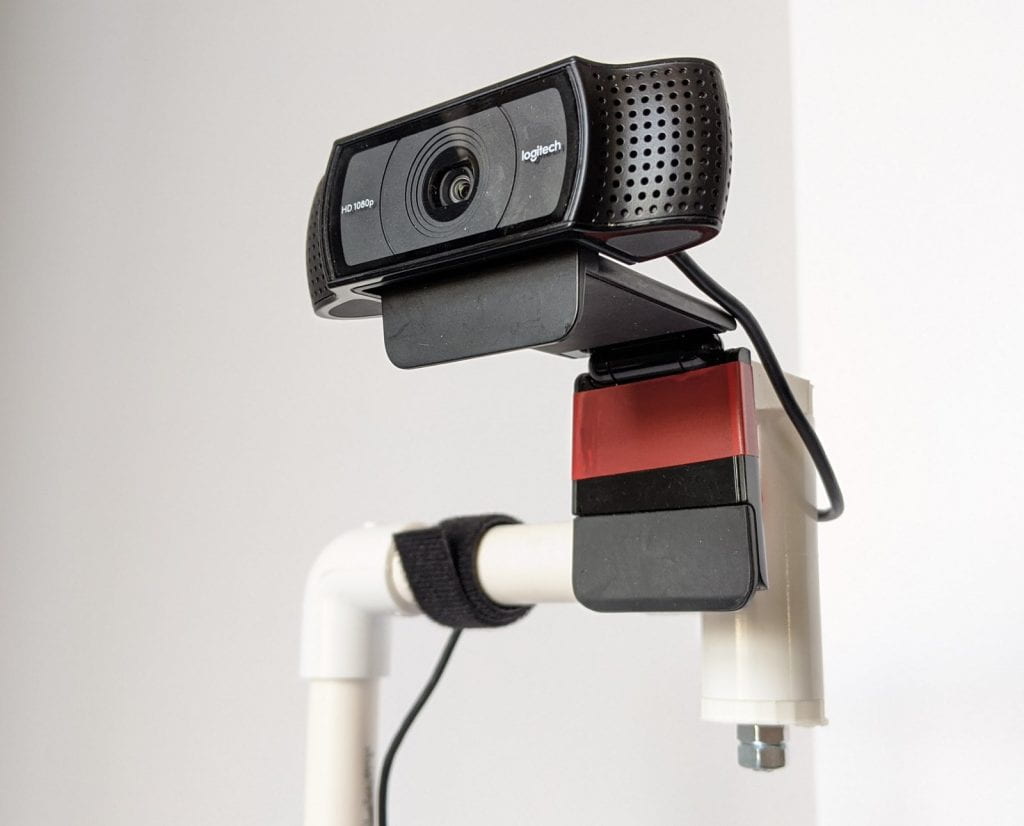
Detail, WebDocCam in webcam mode 
Swivel head around and tilt camera down to use as document camera 
Detail, swivel head in document camera head 
All parts excluding clipboard 
Head parts 
View whole picture to see procedure for inserting the thumbscrew 
Tape around swivel core modulates friction 
How it fits
Printing the base: I used settings 20% infill with 3 shells top and sides, 2 shells bottom, with brim for flattest printing. No supports. The nomenclature and settings of your slicing software will vary.
Printing the head parts: Same settings as the base, only no brim.
Adhesives: I assume if you have a 3D printer you have your favorite adhesives. I used epoxy to join the vertical to the base, but I suppose super glue would work as well. PVC cement to join the PVC parts, and a spot of hot-melt glue to position the rotation-limiting collar on the swivel head.
Connecting the vertical to the base: Place base on plastic sheet. Prepare vertical support by sanding bottom 3cm, coat with epoxy, coat inside of vertical collar of base with epoxy, join, leave overnight.
Camera swivel mount: Place thumbscrew collar between round and flat sections with hex inset facing round. Insert 3/4 – inch bolt and press into collar. Wrap 6.5 cm piece of blue tape around round section for friction (longer for more friction, shorter for less). Insert into top opening of T-fitting, and plug into bottom opening. Insert 3.5-inch lag bolt top-to-bottom, add washer and 2 nuts. The bolt is there to keep everything in alignment and distance, but still allow free rotation, so it doesn’t need to be ‘tight’. Lightly finger-tighten inside nut. Follow with outside nut, lock nuts together using 2 wrenches.
T-fitting: This PVC part is the outer shell of the swivel. Straight-through section takes vertical orientation.
Alignment collar: install on horizontal part of T with arms toward head as shown. Purpose is to limit rotation of swivel for easier operation. Use epoxy or hot-melt glue to secure.
Final assembly: Assuming epoxy that joins vertical to base has set. Apply PVC cement to one side of elbow and press on to top of vertical. While that joint is setting, test the swivel friction and add or remove tape to taste. Apply PVC cement to inside of side hole and press in 12cm cantilever. Wait a moment for joints to firm up. Now apply PVC cement to inside of horizontal part of elbow joint, and press in head assembly – QUICKLY aligning vertical as shown before cement sets. Let assembly become solid.
USE: Mount webcam on swivel head. Allow a loop of cable at top to avoid straining cable, secure to cantilever and vertical with 2 or 3 pieces of Velcro. Swivel and adjust as shown for use as doc cam or web cam.
STL FILE for printable parts: I’m now posting all my STL files on a single page: 3D Printing Files.